#Hardware
The hardware of the Chimaera so far consists of two types of printed circuit boards and an optional enclosure.
#Circuitry
#Sensor Unit (SU-16)
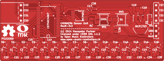

The circuitry for a single sensor unit is pretty simple, it's 16 A1304 linear hall-effect sensors (S0-S15) multiplexed to one output by a 16:1 multiplexer (CD74HC4067). The analog output of each sensor is connected to one input of the multiplexer. The multiplexer has one analog output whose connection to a given input is controlled by the four digital channel selects (CS0-CS3) driven by the DSP unit.

The analog output of the multiplexer is the positive input (Vin) of the OpAmp (U1), which acts as a shifting non-inverting amplifier. It amplifies the signal at its positive end (Vin) relative to a reference voltage (Vref). The output of the OpAmp (Vout) can be sent over the wire as low-impedance input for an analog-to-digital converter. The OpAmp's is embedded in a single package (MCP601).
The analog signal thus can be influenced at two points, e.g. at the trim potentiometers RV1, RV3:
- RV3 acts as a voltage divider, where the reference voltage (Vref) can be set from Vee to Vcc. This is needed because the hall-effect sensors respond to both north and south polarized magnetic fields. With no applied magnetic field, the sensors output is roughly half of its input voltage, this is called the quiescent voltage of the sensor. In a south polarized magnetic field, the voltage linearly approaches Vcc and in a north polarized magnetic field, the voltage linearly approaches Vee. In the case where we want to amplify output voltage in both north and south polarized magnetic fields, the reference voltage (Vref) needs to be set to the mean quiescent voltage of all 16 sensors. This is the default setup of the sensor units in the Chimaera. But there may be usage scenarios where you are interested in only one of the two possible polarizations of the magnetic field and you would like to map it to the whole voltage range for higher resolved ADC performance. In this case you would set the reference voltage (Vref) to either Vcc or Vee.
- RV1 acts as a varistor, setting the amplification factor in conjunction with the fixed resistor R1. The amplification factor is given by 1 + RV1/R1 and can vary from x1 to x11 when using the default components.
Each sensor unit has its own 3.3V low-drop-out voltage regulator to drive the whole circuitry (MCP1703). This makes the unit modular, reduces noise considerably and helps to distribute the generated heat over the whole array of interconnected units. The board's dimensions are 80x30 mm.
You still want to know more? Then get directly to the KiCAD design files at our hardware repository.
#Digital Signal Processing Unit (DSP-F3)
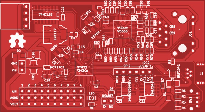

The Chimaera DSP unit is a mixed-signal board. It uses a 32bit ARM Cortex M4 microcontroller from STMicroelectronics (STM32F303Cx) clocked at 72MHz. Of the available peripherals, we use the FPU, ADC1, ADC2, ADC3, SPI1, I2C2, DMA1, DMA2, USB, several TIMERS and a couple of GPIOs. The main circuitry runs at 3.3V, driven by a low-drop-out voltage regulator (LM1117). To leverage the MCU, we use a hardwired UDP/TCP/IP/PHY chip from WIZnet (W5500) which takes care of all the low-level networking and is communicated to via SPI1. There are two EEPROMS (24LC64, 24AA025E48) which store the MAC address, the configuration and the sensor calibration data of the Chimaera. To switch the multiplexers on the sensor units we use a 4-bit counter (74HC163).
The analog part of the board consists of 10 analog inputs which provide connection points to connect up 10 (surprise!) sensor units, leading to a maximum of 80cm of sensor array (160 sensors). Those analog inputs go directly to three in parallel running 12bit ADCs embedded on the MCU. In order to reduce noise, The ADC circuitry on the MCU is driven by a dedicated low-drop-out voltage regulator (MCP1703). The sensor units are connected to by 3 wires (Ain, GND, Vout).
Finally there are a RJ45 MagJack and a mini USB socket. USB is solely used to flash the MCU with new firmware. There are also two SPST buttons to reset the board and to get it into flash mode. The whole board needs to be driven with Vin = 6VDC @250mA minimally. The amperage of the whole Chimaera is calculated as 250mA + n*110mA, where n is the number of sensor units. The board's dimensions are 80x44 mm.
You still want to know more? Then get directly to the KiCAD design files at our hardware repository.
#Accessories
#Magnetic Plektrum (MPlek)
We have designed a simple ring to easily stick the permanent magnets to your fingers. We call it a magnetic plektrum (MPlek). Is is not worn like a normal ring as it is only stuffed over your phalanx media and it is assembled with an accompanying neodymium magnet of specific size in order to be functional.

MPlek with place for a rectangular Neodymium magnet of dimensions 20x4x3mm (LxWxH).
#Magnetic Stamp (MStamp)
We have also designed an alternative holder for the needed magnet in the form of a small stamp. It is intended for use cases where the player would prefer a more loose attachment to the magnet.

Mstamp with place for a rectangular Neodymium magnet of dimensions 20x4x3mm (LxWxH).
You still want to know more? Then get directly to the CAD design files at our hardware repository
#Lasercut Case (L-Case)

Chimaera-S144 case with simple line engraving.

Chimaera-S144 case with neutral line engravings.

Chimaera-S144 case with piano key engravings.

Chimaera-S144 case with piano key engravings and standard paint job.

Chimaera-S144 case with piano key engravings and alternative 6:6 paint job.
The enclosure was designed with different playing styles in mind: it can be put flat on a table like a keyboard, strapped around like a guitar or used standing upright like a cello. As the instrument is played with the hands and fingers, we wanted to have an agreeable touch, which lead us immediately to wooden materials. Thin (2-3 mm) air-plywood is the material of our choice. It can easily been laser-cut. We use a base rip construction in which the printed circuit boards and cable connections are embedded. The rip construction then is wrapped with a kerf-bent plywood sheet. This gives us a robust, ultra-light construction with rounded edges ready to be rocked on.
The case is engraved with short reference lines (each 5 mm) to represent the underlying sensors (they are right below the markings). Additionally there are longer reference lines after 3 sensors each corresponding roughly to the width of a standard piano key (15 mm). As this is a continuous music controller, the lines per se have no meaning, they are meant to help orienting on the virtual continuous string. Their meaning is dependent on the musical mapping of the software/hardware you steer with the Chimaera.
Above there are different schematics of the wrapping plywood sheet for a device with 9 sensor units (144 sensors). If we configure our software synthesizer to map the continuous range to 4 octaves (4*12=48 half-tones), the long lines represent a standard keyboard layout (144/3=48 half-tones). But we may want to map our range to 8 octaves, 1 octave or 1 note only. It therefore makes not always sense to paint a standard piano key layout onto the device, it would only suit one given configuration and interfere with many others. We want the user to decide what the lines mean in their specific setup, the advanced player may ignore them altogether and play solely with the help of hearing and muscle memory.
We have therefore come up with different styles of engravings and paint jobs to accustom different needs of players.
The case design consists of a couple of ECMA scripts for QCAD. The script assembly is adaptable with an overseeable amount of variables, the most important ones being: number of sensor units, material thickness, material tolerance, bolt and nut dimensions.
You still want to know more? Then get directly to the CAD design files at our hardware repository.